Introduction: The Evolution of Industrial Wastewater Treatment
With shrinking water supplies and tightening discharge limits, the industrial sector is facing a massive shift. We can no longer treat wastewater as a waste product; it has become a critical resource for reclamation. This urgency is what has pushed Membrane Bioreactor (MBR) technology to the forefront of modern engineering.
Replacing the Secondary Clarifier
For decades, Conventional Activated Sludge (CAS) was our standard for biological treatment. However, CAS relies entirely on gravity settling in a secondary clarifier—a process notorious for sludge bulking, massive footprints, and inconsistent effluent quality.
MBR eliminates this bottleneck. By replacing the secondary clarifier with physical microfiltration or ultrafiltration membranes, it achieves absolute solid-liquid separation. The result is consistent, crystal-clear water, regardless of how well the sludge settles.
From Niche to Mainstream
Historically, MBR was seen as a luxury. Early industry data and overviews on platforms like Wikipedia show it was treated as a niche alternative, reserved only for high-budget projects or extreme space constraints.
That is no longer the case. Driven by falling membrane costs and corporate Zero Liquid Discharge (ZLD) mandates, MBR has seen explosive market growth. Today, it is no longer an alternative—it is the global standard for industrial water reuse and high-performance wastewater treatment
Process Configuration: Submerged vs. Sidestream MBR
When selecting an MBR system, the first major decision comes down to configuration: should you submerge the membranes directly inside the bioreactor, or run the mixed liquor through an external loop? Both designs achieve identical filtration goals, but their mechanical approaches and operational costs are completely different.
Submerged (Internal) MBR: Vacuum-Driven Efficiency
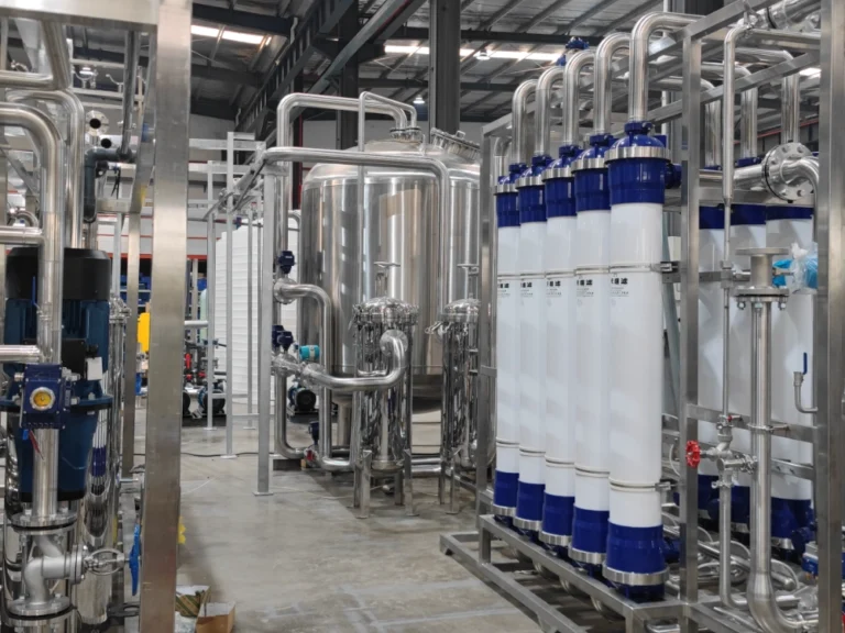
In a submerged configuration, the membrane modules are lowered directly into the biological tank or a dedicated membrane cassette. Instead of pushing water through the membrane, we use a suction pump to create a negative pressure (vacuum), pulling the clean permeate out while leaving the biomass behind.
To prevent the membranes from clogging, we install a coarse bubble aeration system right underneath the modules. The constant upward rush of air shakes the membrane fibers and scours away the accumulated solids. It’s a highly efficient setup for large-scale operations because it uses relatively little power for water delivery, though dealing with chemical cleaning (in-situ CIP) requires some careful handling.
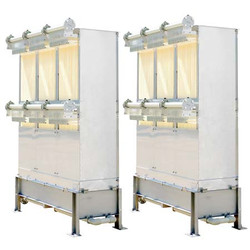
Sidestream (External) MBR: Pressure-Driven Power
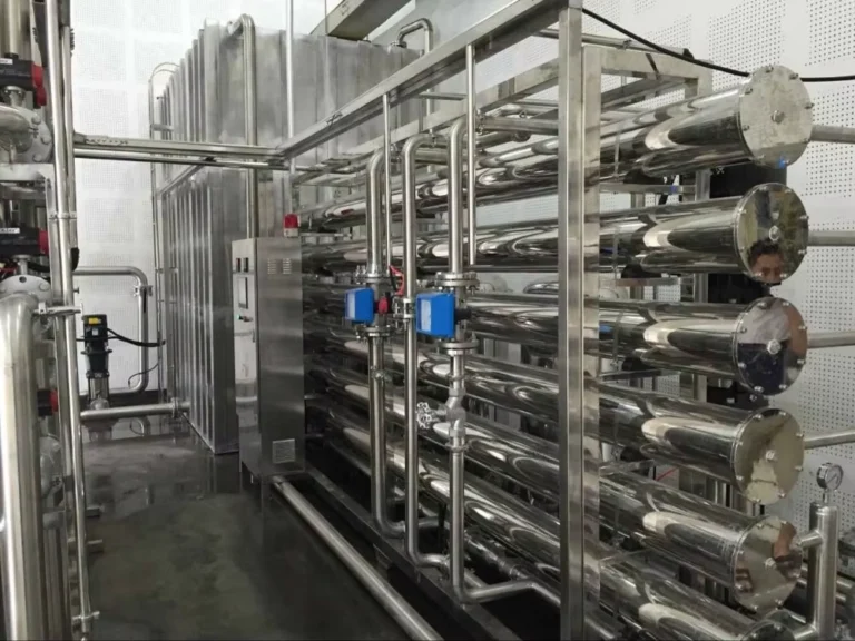
A sidestream system takes the opposite approach. The membranes live outside the bioreactor in a standalone skid. We use high-capacity pumps to drive the mixed liquor under pressure from the biological tank, through the external membrane loop, and back again.
Because we rely on a high cross-flow velocity rather than air bubbles to scour the membranes, sidestream systems eat up significantly more energy. However, what you lose in power efficiency, you gain in sheer operational simplicity. The entire system sits on a concrete floor at eye level—no crane, no heavy lifting, and no diving into wastewater required for maintenance.
Head-to-Head Comparison: Submerged vs. Sidestream
To help weigh the trade-offs, I’ve broken down the key differences we look at during the plant design phase:
| Operational Feature | Submerged (Internal) MBR | Sidestream (External) MBR |
| Driving Force | Vacuum-driven (Negative pressure suction) | Pressure-driven (High-pressure pumps) |
| Energy Demand | Lower (Typically 0.3 – 0.4 kWh/m³) | Higher (Can exceed 1.0 – 2.0 kWh/m³) |
| Footprint | Extremely compact | Larger (Requires dedicated skid space) |
| Maintenance & Cleaning | Requires heavy lifting equipment or cranes to pull modules out for inspection. | Exceptional convenience. All modules are at ground level with no heavy hoisting needed. |
| Membrane Scouring | Continuous coarse bubble aeration | High cross-flow fluid velocity |
| Best-Fit Application | Medium-to-large scale municipal and industrial wastewater plants. | Low-volume, highly concentrated, or toxic industrial wastewater (e.g., chemical, landfill leachate). |
Material Science: Polymeric (PVDF) vs. Ceramic Membranes
The heart of any MBR system is the membrane material itself. Choosing the right material dictates not just your initial capital expenditure (CAPEX), but also how often your team will be dealing with chemical cleanings, membrane fouling, and replacements down the road.
Why Ultrafiltration (UF) Over Microfiltration (MF)?
In MBR applications, we almost always favor Ultrafiltration (UF) over Microfiltration (MF). While both can technically separate biomass from water, MF pores are larger, making them highly susceptible to internal pore clogging caused by extracellular polymeric substances (EPS) and fine colloidal particles.
We typically design systems around a UF membrane with a Molecular Weight Cut-Off (MWCO) of 100 to 200 kDa. This tighter pore structure provides a much cleaner physical barrier. Because the contaminants cannot physically enter the pores, any fouling stays on the outer surface of the membrane. This surface layer is far easier to remove via standard backwashing and scouring, resulting in a much lower overall fouling tendency.
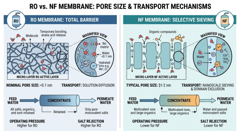
Why Spiral-Wound Membranes Are Strictly Banned
Before comparing materials, it’s worth addressing a common design pitfall: membrane geometry. While spiral-wound elements are the standard for Reverse Osmosis (RO) and clean water applications, they are completely unusable in an MBR tank.
MBR mixed liquor contains massive amounts of Suspended Solids (MLSS), often ranging from 8,000 to 12,000 mg/L. Spiral-wound elements rely on narrow feed spacers that would instantly choke, clog, and fail within minutes of exposure to this sludge. For MBR, we strictly stick to geometries built for high solids: Hollow Fiber (HF) or Flat Sheet (FS).
Material Showdown: PVDF vs. Ceramic
When it comes to the actual material formulation, the market is primarily split between advanced polymers and high-durability ceramics.
PVDF: The Dominant Industry Standard
Polyvinylidene Fluoride (PVDF) remains the absolute dominant choice for commercial MBR installations worldwide. It strikes a near-perfect balance between performance and cost-efficiency.
-
Pros: PVDF offers exceptional chemical resistance, allowing it to withstand aggressive chlorine shocks (NaOCl) and organic acid cleanings during Clean-in-Place (CIP) cycles. It also provides excellent mechanical flexibility, which is crucial for hollow fiber membranes that need to withstand constant movement during air scouring without snapping.
-
Cons: As a polymer, it will eventually degrade, wear down, or suffer from occasional fiber breakage over a 5-to-8-year lifecycle.
Ceramic (Al₂O₃, SiC): The Heavy-Duty Alternative
Typically manufactured from Aluminum Oxide ($Al_2O_3$) or Silicon Carbide (SiC), ceramic membranes represent the premium tier of filtration.
-
Pros: Ceramics are practically indestructible. They feature zero risk of fiber breakage, can tolerate extreme temperatures, and handle pH ranges from 0 to 14. You can clean them with aggressive solvents or backwash them at pressures that would tear a polymeric membrane apart. Their operational lifespan can easily exceed 15 to 20 years.
-
Cons: The primary bottleneck is the initial CAPEX. Ceramic systems require a significantly higher upfront investment compared to PVDF, making them harder to justify unless you are dealing with highly aggressive, oily, or high-temperature industrial wastewater where polymers fail.
Critical Operating Parameters: Moving Beyond Historical Designs
Many of the common complaints about MBR technology—such as rapid membrane fouling, massive energy bills, or dead biomass—stem from outdated engineering mindsets. Early MBR designs operated on overly conservative or theoretical models that simply don’t align with modern field data. By updating our operational parameters to reflect current best practices, we can achieve high-efficiency treatment while significantly lowering operational costs.
Here is a breakdown of the core operating parameters we use to optimize modern industrial MBR systems:
Mixed Liquor Suspended Solids (MLSS): 10,000 – 15,000 mg/L
One of the most significant advantages of an MBR is its ability to operate at much higher biomass concentrations than standard systems. While conventional activated sludge (CAS) processes bottleneck at around 3,000 to 4,000 mg/L due to clarifier settling limitations, a modern MBR easily runs at 10,000 to 15,000 mg/L.
Operating within this optimal range maximizes your volumetric loading rate, allowing the system to handle heavy industrial organic loads in a fraction of the tank volume. Pushing the MLSS above 15,000 mg/L is a classic mistake; it spikes the mixed liquor viscosity, which chokes oxygen transfer and forces the air scouring pumps to work twice as hard.
Solids Retention Time (SRT): 10 – 20 Days
In the early days of MBR adoption, it was common practice to run systems with an extremely long Sludge Age—sometimes exceeding 60 to 100 days—under the false assumption that it would eliminate sludge production entirely. Today, we know that approach does more harm than good.
An excessively long SRT leads to severe biomass compaction, high extracellular polymeric substance (EPS) accumulation, and a high percentage of dead cell debris. This debris rapidly fouls the membrane. Modern best practice limits the SRT to 10 to 20 days. This keeps the bacteria in a highly active, healthy growth phase, maintains low fouling tendencies, and drastically improves oxygen transfer efficiency ($alpha$-factor).
Hydraulic Retention Time (HRT): 3 – 10 Hours
Because the membrane guarantees absolute solid-liquid separation, we can completely decouple the Hydraulic Retention Time from the Sludge Retention Time. For most industrial wastewater streams, we design for a highly compressed HRT of 3 to 10 hours.
This tight window is made possible by the high MLSS concentration—more active biology in the tank means you need less time to break down the incoming Chemical Oxygen Demand (COD). This directly translates to smaller tank geometries, lower civil engineering footprints, and reduced upfront construction costs on site.
Overcoming the Fouling Barrier: Maintenance & Optimization
Let’s be honest: no matter how advanced your membrane chemistry or system design is, membrane fouling is an inevitable reality in wastewater treatment. It’s the single biggest operational headache for plant managers. Over time, suspended solids, colloidal matter, and bacterial slime deposit onto the membrane surface, driving up your Transmembrane Pressure (TMP).
The goal isn’t to prevent fouling entirely—that’s impossible. The goal is to manage it effectively. Through a combination of fluid dynamics and standardized Operations and Maintenance (O&M) protocols, we can control the fouling rate and maintain steady flux for years.
Air Scouring and Two-Phase Flow Control
Our first line of defense is purely mechanical and happens continuously during the filtration cycle. For submerged systems, we rely on coarse bubble aeration directly beneath the membrane cassettes.
This aeration creates a turbulent, upward-moving two-phase flow (air and water mixed). As the bubbles rise along the membrane surface, they generate a high shear stress that physically scours away loose sludge cake before it can compact. Optimizing your air-to-water ratio here is a fine balancing act: too little air leads to rapid clogging, while too much air wastes energy and can physically fatigue the membrane fibers over time.
Backwashing: Managing Daily TMP Rise
To prevent the temporary fouling layer from becoming a permanent bottleneck, the system must run on a programmed, cyclical backwash schedule. Typically every 10 to 12 minutes, we pause the filtration cycle for about 30 to 60 seconds.
During this window, we reverse the flow, pumping clean permeate back through the membrane pores from the inside out. This physical backthrust pops the accumulated cake layer off the membrane surface. Monitoring the baseline TMP immediately after a backwash cycle is our best diagnostic tool; if the post-backwash TMP steadily creeps upward over time, it’s a clear signal that physical cleaning is no longer enough and chemical intervention is needed.
Chemical Cleaning: CIP Protocols for Organic vs. Inorganic Scales
When physical scouring can no longer restore the target flux, we initiate a Clean-in-Place (CIP) cycle. Depending on whether you are running a maintenance clean (low concentration, high frequency) or a recovery clean (high concentration, low frequency), the chemicals we use target two entirely different types of fouling:
Organic and Bio-Fouling Elimination
-
The Chemical: Sodium Hypochlorite ($NaOCl$).
-
The Process: Extracellular polymeric substances (EPS) and live bacterial biofilms form a sticky layer that glues sludge to the membrane. We use a chlorine wash to chemically burn away this organic matrix. Ensuring the correct free chlorine concentration and soaking time is critical to fully dissolving the bio-layer without exceeding the chemical tolerance limits of a polymeric membrane.
Mineral Scaling Removal
-
The Chemical: Citric Acid or Dilute Inorganic Acids (such as $HCl$).
-
The Process: If your industrial wastewater has high hardness, or if you are dosing coagulants like ferric chloride or alum upstream, minerals will precipitate onto the membranes. This creates a hard, crusty mineral scale that chlorine cannot touch. An acid wash drops the local pH, dissolving calcium carbonate, iron precipitates, and other inorganic salts, cleanly restoring the membrane’s structural permeability.
Industrial Applications & RO Feed Optimization
Because MBR delivers exceptional effluent quality within a minimal footprint, it has become the go-to solution for challenging water reuse projects. In my experience, while a standard system fails when faced with toxic shocks or strict reuse mandates, a properly designed MBR excels.
We primarily deploy MBR systems across three high-stakes applications:
Municipal Water Reclamation in Space-Constrained Areas
As urban areas expand and freshwater costs rise, municipal plants are heavily converting to water reclamation centers. In densely populated regions where buying more land for massive gravity clarifiers is economically impossible, MBR is a lifesaver.
The system fits directly inside existing footprints while producing water clean enough for immediate non-potable reuse. We regularly see MBR effluent sent directly to urban irrigation networks, public parks, industrial cooling towers, and commercial toilet flushing systems, fully meeting the most rigid microbial discharge standards worldwide.
High-Strength Industrial Wastewater & Complex Bio-Degradation
Industrial wastewater from chemical plants, pharmaceutical facilities, and pesticide manufacturers is notoriously difficult to treat. These streams contain recalcitrant organic compounds, harsh herbicides, and complex toxins that would wash away or kill off the biology in a conventional system.
Because MBR utilizes a physical membrane barrier, it decouples the Sludge Retention Time (SRT) from the hydraulic flow. This allows us to maintain an exceptionally high sludge age without losing biomass. This extended SRT fosters a highly specialized, slow-growing, and diverse microbial community. These specialized bacteria develop the specific enzymes needed to break down stubborn, non-biodegradable chemicals that standard wastewater plants simply cannot digest.
The Ultimate Pretreatment for Reverse Osmosis (RO) Systems
For facilities aiming for Zero Liquid Discharge (ZLD) or high-purity industrial water recycling, MBR is rarely the final step. Instead, we use it as the ultimate upstream protective barrier for Reverse Osmosis (RO) networks.
RO membranes are extremely sensitive. If you feed them water with even minor biological activity or suspended solids, they will foul, scale, and fail within weeks.
An MBR system changes the math entirely. Because it uses ultrafiltration membranes, it delivers an effluent with a Silt Density Index ($SDI_{15}$) consistently below 3, along with near-zero turbidity. Feeding this high-quality, particle-free water into an RO system drastically reduces RO membrane fouling, slashes chemical cleaning frequencies, and extends the operational lifespan of expensive RO elements by years.
Engineering a Bespoke MBR Solution
When you look at the raw performance capabilities of modern Membrane Bioreactor systems, the core value proposition for industrial operations becomes undeniably clear. By eliminating the secondary clarifier and decoupling SRT from HRT, MBR allows you to cut your treatment facility’s physical footprint by up to 50% compared to conventional plants. Furthermore, because these systems rely on precise mechanical barriers rather than unpredictable gravity settling, they integrate perfectly with modern, programmable logic controllers (PLCs) and automated chemical dosing networks, drastically reducing daily manual labor costs.
Why Off-the-Shelf Packages Constantly Fail
However, treating MBR as a simple plug-and-play appliance is the fastest way to blow through your O&M budget. Every factory’s wastewater profile is a unique, moving target. A system designed for a municipal water reclamation facility will instantly foul and fail if fed high-salinity pharmaceutical waste or high-temperature chemical streams.
Your specific site infrastructure, incoming Chemical Oxygen Demand (COD) spikes, local chemical costs, and discharge limits demand a balanced engineering approach. While utilizing standardized membrane modules and skid components keeps your initial capital costs low, the surrounding process flow must be completely tailored to your operational realities.
Let’s Build Your System: Next Steps
To get the maximum operational lifespan out of your investment and avoid premature membrane replacement costs, you need a precise engineering evaluation.
For high-strength or highly variable industrial streams, I always recommend initiating a structured pilot testing phase. Running a small-scale, on-site pilot unit for a few weeks gives us the real-world field data needed to map out exact flux rates, identify specific mineral scaling risks, and establish your exact chemical cleaning frequencies before a single piece of full-scale equipment is ordered.
If you are ready to upgrade your existing footprint, transition your facility toward Zero Liquid Discharge (ZLD), or require a robust pretreatment system for your downstream Reverse Osmosis lines, let’s look at your current water data. Reach out today to schedule a technical evaluation with our engineering team, and let’s design a high-performance, bespoke MBR solution built specifically for your plant.